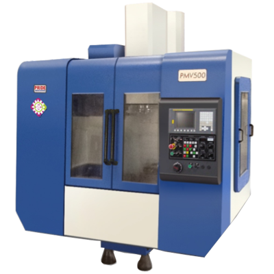
- l LM guides on all 3 axes
VERTICAL MACHINING CENTERS
- Home /
- VERTICAL MACHINING CENTERS
Description

Specifications
|
|
Unit |
PMV-400 |
PMV-500 |
| TABLE | |||
| Table size |
mm |
900 x 425 |
900 x 425 |
| T-Slot dimension |
N x W x P |
4 x 18 x 100 |
5 x 18 x 100 |
| Max. load on table |
kgf |
500 |
500 |
| Distance from floor to table top |
mm |
925 |
850 |
| MACHINE CAPACITY | |||
| X Axis travel |
mm |
550 |
800 |
| Y Axis travel |
mm |
460 |
510 |
| Z Axis travel |
mm |
460 |
510 |
| Distance from spindle face to table top |
mm |
150-610 |
175-685 |
| Distance from spindle center to column guideways |
mm |
540 |
608 |
| SPINDLE | |||
| Spindle nose taper |
7/24 No 40 |
7/24 No 40 |
|
| Spindle speed |
rpm |
60-6000 |
80-6000 |
| Spindle bearing Dia. |
mm |
70 |
70 |
| Tool clamping force |
kgf |
600 |
600 |
| Spindle power (15 min./cont.) |
kW |
11 / 7.5 |
|
| FEED | |||
| Rapid traverse rates X, Y & Z |
m/min |
24 / 24 / 24 |
24 / 24 / 24 |
| Cutting feed |
m/min |
1 to 5000 |
1 to 5000 |
| Ball screw dia. x Pitch X, Y & Z |
mm x mm |
40 x 12 |
40 x12 |
| AUTOMATIC TOOL CHANGER | |||
| Number of tools |
No. |
20 |
20 |
| Max. tool dia. |
mm |
80 |
80 |
| Max. tool dia with adjacent |
mm |
125 |
155 |
| Tool selection |
Bi-directional |
Bi-directional |
|
| Tool length – Max. |
mm |
250 |
250 |
|
kgs |
8 |
8 |
|
| Tool to tool time |
Sec. |
2.5 |
2.5 |
| Chip to chip time |
Sec. |
6.5 |
6.5 |
| Tool change system |
Twin arm |
Twin arm |
|
| Tool shank type |
BT-40 / ISO-40 |
BT-40 / ISO-40 |
|
| Pull stud type |
DIN 69872 From-B |
DIN 69872 From-B |
|
| INSTALLATION DATA |
Sec. |
2.5 |
2.5 |
| Machine width |
DIN 69872 From-B |
DIN 69872 From-B |
|
| Machine depth |
DIN 69872 From-B |
DIN 69872 From-B |
|
| Machine height |
DIN 69872 From-B |
DIN 69872 From-B |
|
| Machine weight net |
kgf |
4000 |
5000 |
| TANK CAPACITY | |||
| Coolant tank |
Ltr. |
200 |
200 |
| Lubrication tank |
Ltr. |
3 |
3 |
| CNC SYSTEM Std. / Opt. |
Ltr |
FANUC / Siemens or Mitsubishi |
FANUC / Siemens or Mitsubishi |
